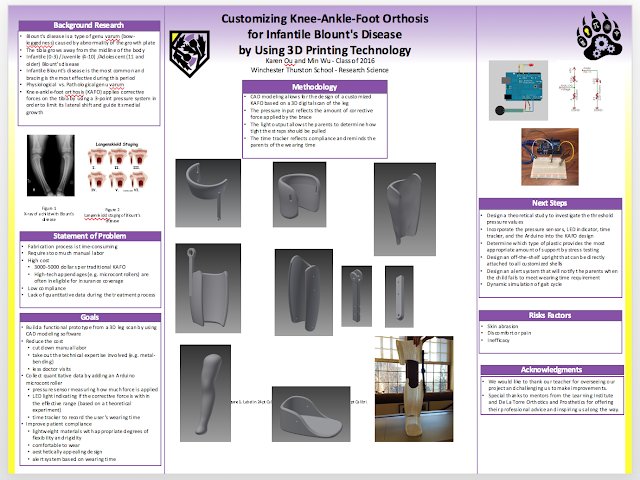
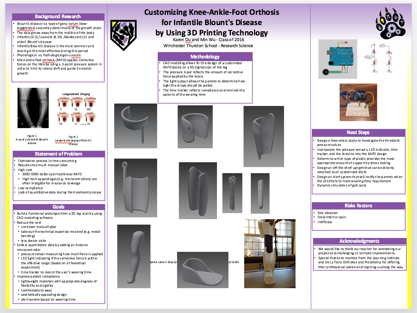
KAFO Design Considerations
A good KAFO compensates for the biomechanical deficits of each patient by providing control at the ankle and the knee. A physical examination is needed to quantitively measure the biomechanical losses of each joint in order to develop a detailed, custom-designed prescription. The orthosis should interfere with the joint motion as little as possible while effectively correcting abnormal ambulation.
When choosing the materials of an orthosis, we need to take into consideration the cost, weight, safety, and functional reliability of the materials. To minimize the weight of the final product, we have several options: thermoplastics are tough and somewhat flexible; carbon fibers are thin, stiff, and lightweight; aluminum alloys are lighter than steel but subject to fatigue failures; titanium alloys provide strength that is similar to steel but is almost as light as aluminum.
The design of the orthosis should be structurally sound, functionally reliable, and also user-friendly (easy to put on/take off). We've learned from our research that KAFOs with an anterior opening are easier to put on than brim-style KAFOs (both quadrilateral brim-style and M-L brim-style). Also, to making donning easier, the thigh/femoral shell and the calf/tibial shell should be open on the same side (although the KAFO is structurally more stable if they're open on opposite sides). In other words, the two shells should both have posterior openings or both anterior openings.
(Click here to read more about different KAFO designs)
With regard to the metal bars connecting the thigh and calf shells, a single, lateral bar provides sufficient support for toddlers since they have small body weight and low activity level.
Click here to view the source
Wednesday, December 9, 2015
Wednesday, December 2, 2015
Weekly Update
12/02/2015
During the past week, our group had been trying to do research and find a mentor who will help us along the way. We are waiting to hear from Dr. Jan Grudziak, a pediatric orthopedic specialist at Children’s Hospital of Pittsburgh.
Information about a newly designed KAFO brace with a different mechanism will be updated under "Types of KAFO".
Tomorrow, we are heading to TechShop for our first vacuum forming class. Hopefully, the class will inform and inspire us to create a brace with the help of the vacuum forming machine.
02/08/2016
Check out newest information on our 2nd CAOC meeting and the third iteration pics under their corresponding tabs.
03/08/2016 Techshop Presentation
To get feedback and critique from professionals, we presented our project at Techshop.
Ratchet?? Transmitter???
03/12-3/27 SPRING BREAK
To build the fourth iteration of our KAFO model, we obtained a 3D leg scan of a four-year-old girl who's not affected by the disease. This time instead of drawing a generic shape of the KAFO, we horizontally sliced the leg and used the "LOFT" feature to create the brace so that it is contoured to the leg scan. The results are promising -- the shape of the KAFO turn out to be a lot more organic than our last iteration and is also much thinner.
04/01 PRSEF
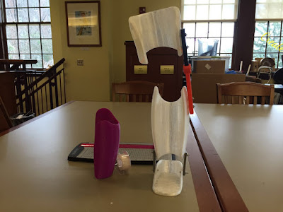
Today we presented our project at the Pittsburgh Regional Science and Engineering Fair and won two awards: a four-year scholarship at Harrisburg University and a Naval Science Award from the Office of Naval Research. At this point we have a functional prototype built upon Karen's leg scan, but we have yet to finish building the latest model based on our teacher's 4-year-old daughter's leg. The Arduino microcontroller now has an LED light which turns on when the pressure detected by the pressure sensor is beyond the threshold values (too high or too low). Our next step is to add straps to the brace and incorporate the pressure sensor into our design.
04/07/2016
Today we finalized our plan for our project for the STEM Symposium on May 19th. Our goals are:
-have our teacher's daughter try on our KAFO and walk in it to get relevant data (i.e. pressure data)
-attempt printing with different materials and different densities
-show display of data (on computer or LCD screen or phone)
During the past week, our group had been trying to do research and find a mentor who will help us along the way. We are waiting to hear from Dr. Jan Grudziak, a pediatric orthopedic specialist at Children’s Hospital of Pittsburgh.
Information about a newly designed KAFO brace with a different mechanism will be updated under "Types of KAFO".
Tomorrow, we are heading to TechShop for our first vacuum forming class. Hopefully, the class will inform and inspire us to create a brace with the help of the vacuum forming machine.
02/08/2016
Check out newest information on our 2nd CAOC meeting and the third iteration pics under their corresponding tabs.
03/08/2016 Techshop Presentation
To get feedback and critique from professionals, we presented our project at Techshop.
Ratchet?? Transmitter???
03/12-3/27 SPRING BREAK
To build the fourth iteration of our KAFO model, we obtained a 3D leg scan of a four-year-old girl who's not affected by the disease. This time instead of drawing a generic shape of the KAFO, we horizontally sliced the leg and used the "LOFT" feature to create the brace so that it is contoured to the leg scan. The results are promising -- the shape of the KAFO turn out to be a lot more organic than our last iteration and is also much thinner.
04/01 PRSEF
Today we presented our project at the Pittsburgh Regional Science and Engineering Fair and won two awards: a four-year scholarship at Harrisburg University and a Naval Science Award from the Office of Naval Research. At this point we have a functional prototype built upon Karen's leg scan, but we have yet to finish building the latest model based on our teacher's 4-year-old daughter's leg. The Arduino microcontroller now has an LED light which turns on when the pressure detected by the pressure sensor is beyond the threshold values (too high or too low). Our next step is to add straps to the brace and incorporate the pressure sensor into our design.

04/07/2016
Today we finalized our plan for our project for the STEM Symposium on May 19th. Our goals are:
-have our teacher's daughter try on our KAFO and walk in it to get relevant data (i.e. pressure data)
-attempt printing with different materials and different densities
-show display of data (on computer or LCD screen or phone)
Monday, November 23, 2015
CAOC
Real-life story about a little girl's battle against Blount's disease.
Click here to read more about Mckenzie Upton.
12/02/2015
During the past week, our group had been trying to do research and find a mentor who will help us along the way. We are waiting to hear from Dr. Jan Grudziak, a pediatric orthopedic specialist at Children’s Hospital of Pittsburgh.
Information about a newly designed KAFO brace with a different mechanism will be updated under "Types of KAFO".
Tomorrow, we are heading to TechShop for our first vacuum forming class. Hopefully, the class will inform and inspire us to create a brace with the help of the vacuum forming machine.
12/03/2015 TechShop Update
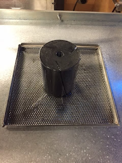
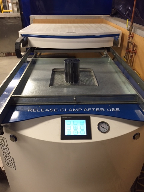
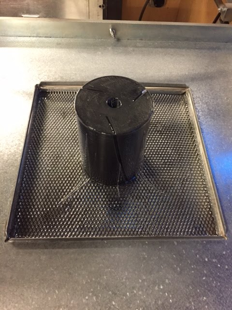
Today we took a vacuum forming class at TechShop. The vacuum forming machine is widely used in commercial packaging and mass production. We wanted to compare vacuum forming to 3D printing and see which technique is more effective and also more efficient at producing a brace off of a leg model. We wanted to use the prosthetic leg Emma made last year for her project as a mold, but they couldn't find us plastic sheets big enough for the leg (although the leg fit perfectly fine on the machine). Therefore, we decided to use a small cylindrical 3D printed object as a mold just to see how the machine worked.
Here is a picture of the mold on the machine:
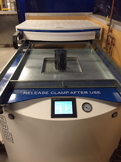
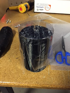
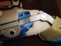
A closer look at the mold and the vacuum-formed product (clear plastic):
We couldn't get the plastic off of the mold so we had to cut open the sides in order to pull it off...
Our biggest takeaway from this class is that vacuum forming may not work for our project because we would need plastic far thicker and sturdier than the one given to us in this class, and we also learned that it's hard to vacuum form certain shapes because the plastic would pop, and it's also incredibly hard to get the vacuum-formed plastic off of the mold. However, if we ever need to produce several models of the leg brace in a short period of time, we might come back to vacuum forming for help.
Click here to watch a video about vacuum forming.
12/11/2015
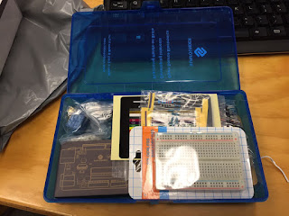
Today we took an Arduino class at TechShop. Each of us obtained a set of materials needed including breadboard, switch, sensors, motor, LEDs and various electronic components. We learned some basic Arduino programming skills and may further apply them onto the leg brace to collect data.
12/15/2015
Today we had a meeting with Peggy Giesen, a pediatric physical therapist from the Learning Institute.
Some thoughts and considerations we learned through the meeting are as following:
01/29/2016
We had a very nice and informative meeting with Sean Greer from DeLaTorre Orthotics.
1. safe, quick digital image capture; require a minimal amount of time for the baby to hold still in order to get a clear image of the leg
Click here to read more about Mckenzie Upton.
12/02/2015
During the past week, our group had been trying to do research and find a mentor who will help us along the way. We are waiting to hear from Dr. Jan Grudziak, a pediatric orthopedic specialist at Children’s Hospital of Pittsburgh.
Information about a newly designed KAFO brace with a different mechanism will be updated under "Types of KAFO".
Tomorrow, we are heading to TechShop for our first vacuum forming class. Hopefully, the class will inform and inspire us to create a brace with the help of the vacuum forming machine.
12/03/2015 TechShop Update
Today we took a vacuum forming class at TechShop. The vacuum forming machine is widely used in commercial packaging and mass production. We wanted to compare vacuum forming to 3D printing and see which technique is more effective and also more efficient at producing a brace off of a leg model. We wanted to use the prosthetic leg Emma made last year for her project as a mold, but they couldn't find us plastic sheets big enough for the leg (although the leg fit perfectly fine on the machine). Therefore, we decided to use a small cylindrical 3D printed object as a mold just to see how the machine worked.
Here is a picture of the mold on the machine:
A closer look at the mold and the vacuum-formed product (clear plastic):
We couldn't get the plastic off of the mold so we had to cut open the sides in order to pull it off...

Our biggest takeaway from this class is that vacuum forming may not work for our project because we would need plastic far thicker and sturdier than the one given to us in this class, and we also learned that it's hard to vacuum form certain shapes because the plastic would pop, and it's also incredibly hard to get the vacuum-formed plastic off of the mold. However, if we ever need to produce several models of the leg brace in a short period of time, we might come back to vacuum forming for help.
Click here to watch a video about vacuum forming.
12/11/2015
Today we took an Arduino class at TechShop. Each of us obtained a set of materials needed including breadboard, switch, sensors, motor, LEDs and various electronic components. We learned some basic Arduino programming skills and may further apply them onto the leg brace to collect data.

12/15/2015
Today we had a meeting with Peggy Giesen, a pediatric physical therapist from the Learning Institute.
Some thoughts and considerations we learned through the meeting are as following:
- Gait Pattern
- Medial/Lateral metal bar
- No quantitative data; redness & marking
- Locking the hinge
- Room for growth; easy adjustments
- both sides of ankle and knee; bony prominences-->soft padding
- foot plate; foot position
- orthosis inside the shoe
- Bilateral/unilateral-->leg length discrepancy; add height to shoe
- Compliance
01/29/2016
We had a very nice and informative meeting with Sean Greer from DeLaTorre Orthotics.
He is a Certifed Orthotist with DeLaTorre Orthotics and Prosthetics. He specializes in pediatric bracing, especially body remolding devices such as cranial remolding helmets, scoliosis braces, and Blount's braces.
Notes from the meeting:
Goals: build a theoretical model which allows the following:
2. make the brace more appealing to parents-->increase compliance
- thickness of the brace
- fits inside the pant and shoe; “invisible”
- aesthetically appealing design
- room for growth→ less frequent visits, no need to make newer braces and thus reduce cost, avoid ?? nerve (beneath: where corrective force is exerted; above: better); however, more space means less control and less fitting
3. take technician out of the equation→ reduce medical expertise required in the fabrication process and thus lower the cost
5. 3-point pressure system
-What is the threshold pressure value below which the kafo is no longer effective?
-Does this pressure correlate with age (critical window: 18-30 months) ?
-green→ within the pressure range
-yellow→ too tight
- expertise needed for scanning and making adjustments to make sure the brace is working appropriately
- now: the shells are contoured to the shape of the bones and the upright is bent in order to align the shells
- metal bending is becoming a dying art; adds to cost→ off-the-shelf components (esp. straight aluminum upright) are to be attached directly to the customized shells while maintaining the straight alignment of the brace→ protruding rectangular platform
- 90% polypropylene (rigidity) and 10% polyethylene (flexibility)
- light, portable, doesn’t cause skin breakdown
- conditionally malleable? 4D printing: becomes bendable when heat is applied→ change shape to accommodate growth click
- Davis’ and Wolff’s laws of tissue adaptation and bone remodeling: inhibited growth where pressure is exerted
- exert pressure on the proximal, lateral side of tibia
- pressure sensor & alert system
- How tight should the straps be pulled? → make the call based on feeling (loosen the straps when a bruise/blister/open wound results)
- design a longitudinal study to investigate…
-What is the threshold pressure value below which the kafo is no longer effective?
-Does this pressure correlate with age (critical window: 18-30 months) ?
- place a pressure sensor on lateral side of tibial shell to measure much pressure is applied when the strap below the knee is pulled this tight
- color lights indicating how tight the strap is pulled:
-green→ within the pressure range
-yellow→ too tight
Tuesday, November 17, 2015
Different KAFO Designs
There are several different models of Blount's KAFO, but the general structure of each brace is the same -- there are five main components: a thigh/femoral cuff, a calf/tibial shell, a foot piece, one or two metal bars connecting the thigh cuff and the calf shell, and a few straps that secure the brace on the leg. The goal of every KAFO designed for Blount's disease is also the same, which is to exert corrective forces on the misaligned bones through several points of pressure and to guide the normal growth of tibia.
Model 1:


This double upright (two metal bars) brace has a quadrilateral brim-style thigh cuff, and its calf part has a posterior opening with a partial pretibial shell. There are two metal bars connecting the thigh cuff and the calf shell.
click on this link for more info on model 1.
Model 2:


This model is different from model 1 in that its thigh cuff has an anterior opening and is held in place by two straps. The calf piece is open in the front as well, and it looks like the calf and the foot are one piece. Note also that the upper and lower parts of this KAFO have irregularly curved edges (the thigh piece is longer on the medial side and the calf piece is longer on the lateral side).Two metal bars join the upper and lower parts of this brace. This is an example of the double upright M-L anterior opening KAFO.
Model 3:


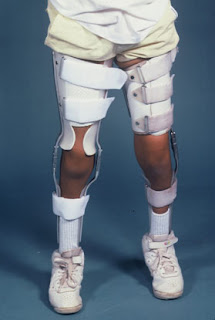
This model looks a lot simpler and lighter than the previous two models. The main differences are that there is only one metal bar connecting the thigh cuff and the calf shell and there are only two straps.


more pictures of model 3...
Click on this link for more info on model 3.
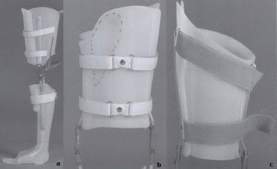
This picture shows different designs of the thigh shell. (a) is an anterior opening KAFO with a pretibial shell. (b) is a KAFO with a quadrilateral brim style. (c) is a narrow M-L brim style KAFO. Research shows that it's easier to put on the KAFO in (a) than those in (b) and (c).
Model 1:
This double upright (two metal bars) brace has a quadrilateral brim-style thigh cuff, and its calf part has a posterior opening with a partial pretibial shell. There are two metal bars connecting the thigh cuff and the calf shell.
click on this link for more info on model 1.
Model 2:
This model is different from model 1 in that its thigh cuff has an anterior opening and is held in place by two straps. The calf piece is open in the front as well, and it looks like the calf and the foot are one piece. Note also that the upper and lower parts of this KAFO have irregularly curved edges (the thigh piece is longer on the medial side and the calf piece is longer on the lateral side).Two metal bars join the upper and lower parts of this brace. This is an example of the double upright M-L anterior opening KAFO.
Model 3:
This model looks a lot simpler and lighter than the previous two models. The main differences are that there is only one metal bar connecting the thigh cuff and the calf shell and there are only two straps.
more pictures of model 3...
Click on this link for more info on model 3.
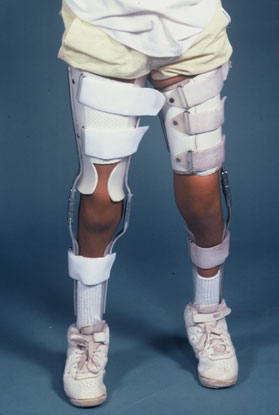
This picture highlights the difference between single-upright and double-upright KAFOs.
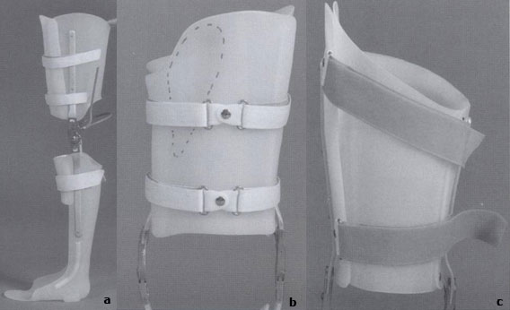
This picture shows different designs of the thigh shell. (a) is an anterior opening KAFO with a pretibial shell. (b) is a KAFO with a quadrilateral brim style. (c) is a narrow M-L brim style KAFO. Research shows that it's easier to put on the KAFO in (a) than those in (b) and (c).
Monday, November 16, 2015
Tutorials
We found the following links interesting:
Click on this link shows some basic understanding of the factors appropriately and efficiently treat children with Blount's Disease.
Click on this link is about using 3D printing to create a lightweight leg brace which is similar to our idea for the project.
Click on this link shows some basic understanding of the factors appropriately and efficiently treat children with Blount's Disease.
Click on this link is about using 3D printing to create a lightweight leg brace which is similar to our idea for the project.
Design Process
Ultimate Goals for our leg brace:
Steps to accomplish the goal:
- Lighter weight
- Correct gesture and strength leg muscles
- Include sensor which can indicate the steps and time the user has produced
Steps to accomplish the goal:
- Use 3D model to create a basic structure of the leg brace.
- Build upon the design and try to improve.
- Utilize the resources from the TechShop.
- Finalize the design.
- Do test runs and collect the data from leg brace.
- Add pressure points and sensor.
Subscribe to:
Posts (Atom)